A pressure vessel is not something you “just fabricate” — it is safety‑critical equipment that must perform reliably under pressure, temperature, cyclic loading, and real‑world plant conditions. Done properly, pressure vessel manufacturing turns design intent into certified, traceable hardware that can be installed with confidence and operated for years with predictable integrity. If you are specifying equipment for an oil and gas, chemical and petrochemical, or wider industrial project, understanding the manufacturing process helps you ask better questions, reduce rework, and protect schedule.
What Is a Pressure Vessel?
A pressure vessel is a container designed to contain gases or liquids at a pressure substantially different from ambient pressure. Because stored energy can be hazardous, vessels are typically designed and built to recognised safety standards and codes such as the ASME BPVC (ASME Boiler and Pressure Vessel Code), including Section VIII, EN 13445, or regional frameworks such as PED in Europe, depending on service, location, and classification.
In practical terms, pressure vessel manufacturing is about more than a single weld — it is a controlled, quality‑led manufacturing process that combines design and engineering, material selection, forming, fabrication, testing and inspection, and documentation into one traceable route.
The Pressure Vessel Manufacturing Process (High-Level Steps)
Most projects follow the same core sequence:
- Design basis, code route, and technical specifications
- Vessel design detailing and drawings
- Raw material procurement and traceability control
- Cutting, forming, and fit‑up
- Welding process execution and weld quality control
- Non‑destructive testing and inspection
- Heat treatment / post weld heat treatment (where required)
- Machining of interfaces and dimensional verification
- Hydrostatic testing (or pneumatic test where justified)
- Surface preparation, coating, and final finishing
- Certification dossier and handover
The difference between “built” and “built right” is the discipline applied at every stage.
1) Design Basis, Code Route, and Vessel Design Requirements
The project starts by defining the design requirements: specific pressure and temperature, fluid type (gas or liquid), corrosion allowance, cyclic duty, allowable stress, and operational requirements such as cleaning, insulation, or external loads. This is also where the ASME code or equivalent route is confirmed and the inspection hold points are agreed.
Typical outputs include:
- Process datasheets for process vessels (design pressure/temperature, volumes, nozzle schedule)
- Code route and classification decisions
- Inspection and test plan (ITP)
- Documentation requirements of the ASME (or applicable code) and client
A reliable fabricator will insist on clarity here, because late changes to nozzle schedules or load cases can cascade into re‑calculation, re‑forming, and re‑welding.
2) Design and Engineering: Drawings, Thickness, and the Vessel’s Shape
Mechanical design converts the basis into wall thickness, nozzle reinforcement, flange ratings, head selection, and support design (skirts, saddles, lugs). The vessel’s shape is selected for the duty and economics: cylindrical shells with formed heads are most common, but geometry can vary for high pressure, extreme temperatures, or space constraints.
Deliverables typically include:
- General arrangement drawings and nozzle orientation
- Fabrication drawings with weld details and tolerances
- Load cases (wind, seismic, lifting) and support calculations
- NDE/NDT extent by joint category
This stage is where long‑term robustness is designed in, especially when the service includes corrosive substances or demanding cyclic operation.
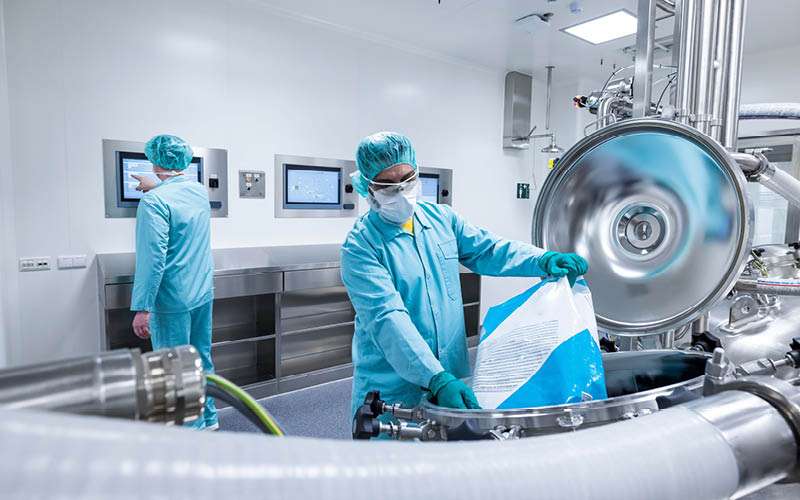
3) Materials Used: Procurement, Traceability, and Incoming Control
Material choice is driven by the chemical process, temperature, pressure, and corrosion environment. Common used materials include carbon steel and stainless steel; higher‑alloy selections may be required for corrosive or high‑temperature service, including nickel alloys such as Hastelloy (often selected for excellent corrosion resistance and strength at elevated temperatures, depending on grade and conditions).
A typical procurement and control loop includes:
- Ordering plate, forgings, and structural shapes to code requirements
- Receiving raw material with certificates and heat number traceability
- Verifying identification, dimensions, and surface condition on receipt
- Maintaining traceability through cutting and welded parts to final nameplate
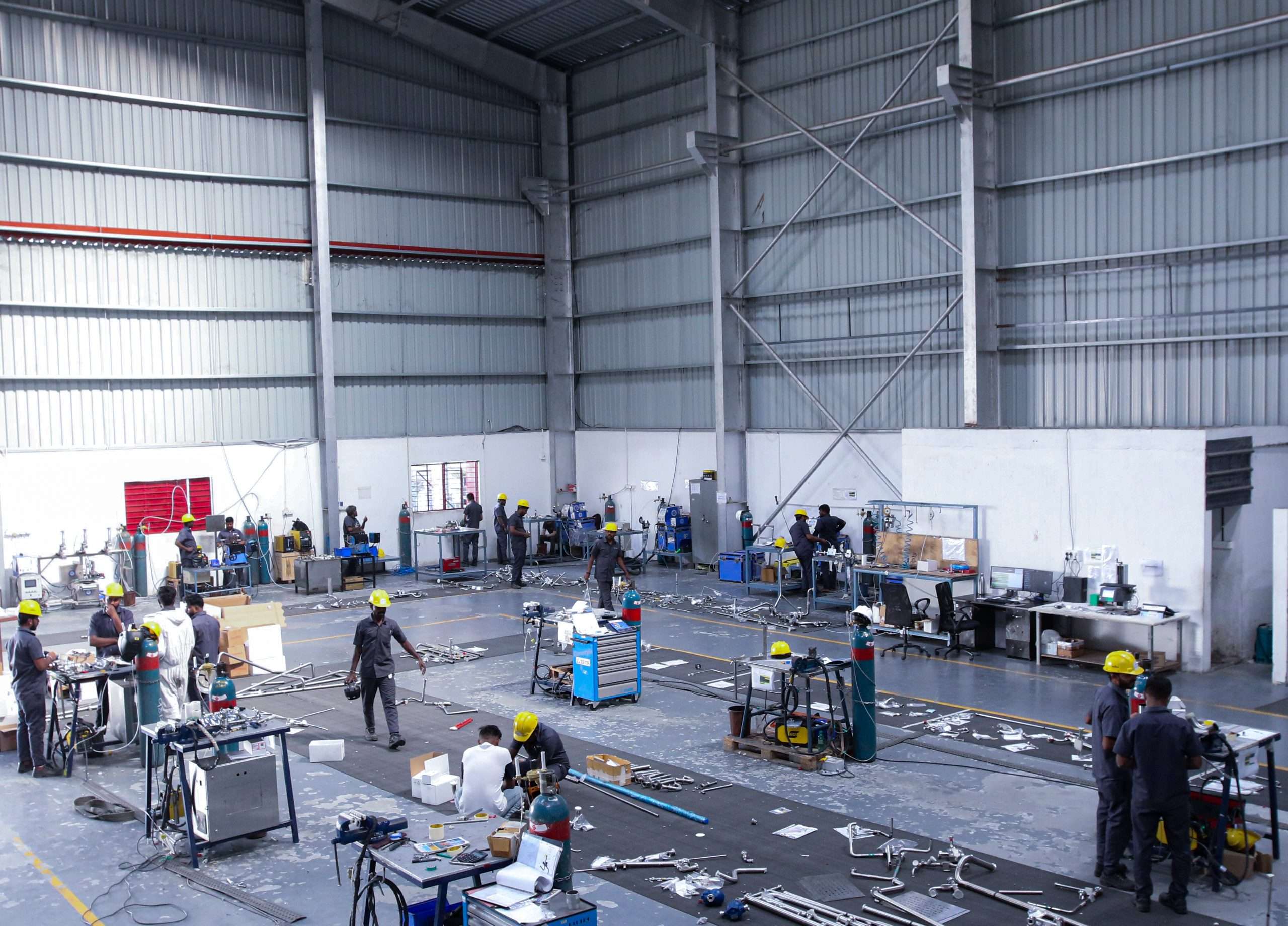
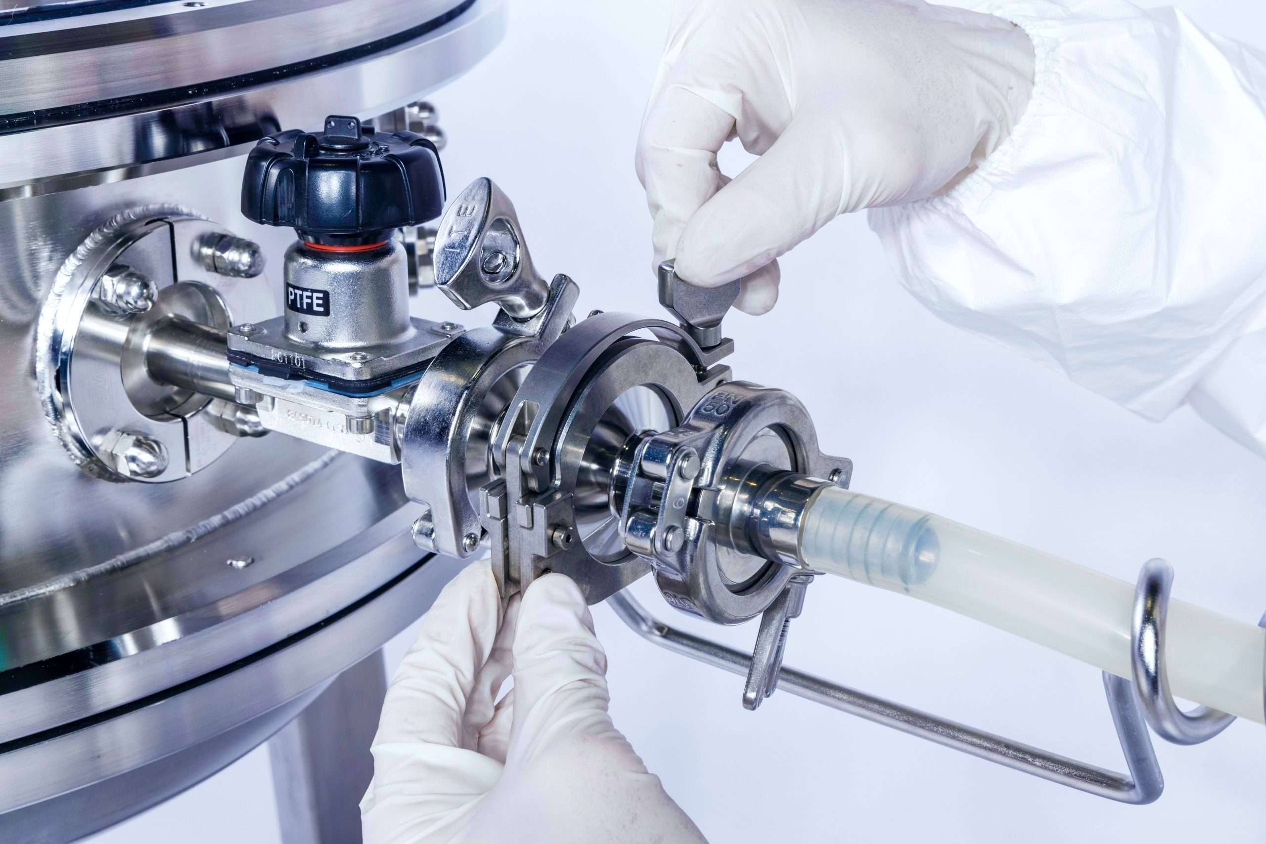
4) Cutting, Forming, Fit‑Up, and Assembly (Fabrication Techniques)
Once released, material is cut and formed into the shell and heads:
- Plates are cut and rolled into cylindrical shell courses
- Heads are pressed/spun to required profiles
- Openings are cut for nozzles, manways, and instruments
Fit‑up quality drives weld quality. Alignment, root gap, cleanliness, and tack control reduce distortion and rework. For multi‑course shells, the circumferential weld sequence and fit‑up tolerances are planned to keep geometry within limits.
Where required, forging is used for nozzles, hubs, flanges, or high‑strength features.
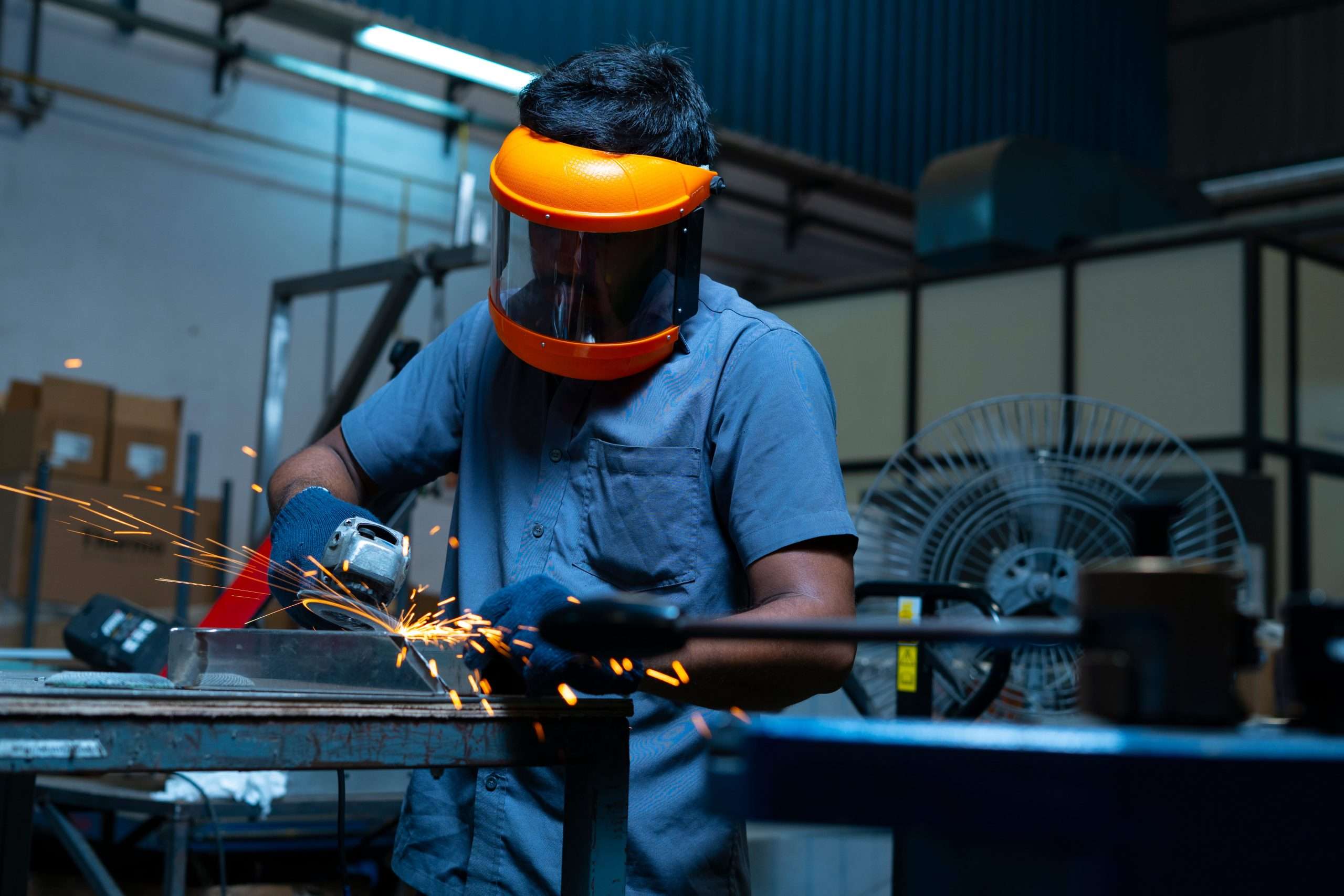
5) Welding Process and Controls (People, Procedure, Equipment)
The welding process is controlled through qualified procedures and qualified personnel:
- Welding procedure specifications (WPS) and qualification records
- A qualified welder working to approved parameters
- Suitable welding equipment and consumables for the material grade
Preheat, interpass temperature, and cleanliness are managed to prevent cracking and maintain properties. For vessels with stainless steel and carbon steel combinations, cladding, or dissimilar joints, the welding plan is often tailored to manage dilution, distortion, and inspection accessibility.
6) Testing and Inspection: Non‑Destructive Examination
Inspection is not a final step — it is integrated throughout fabrication. Visual inspection is continuous, and code‑required non‑destructive examination verifies weld integrity without damaging the component.
Typical non‑destructive testing methods include:
- VT (visual testing)
- PT (dye penetrant)
- MT (magnetic particle)
- ultrasonic testing (UT)
- RT (radiography)
Inspection looks for discontinuity indications and confirms acceptance criteria. Repairs are documented, re‑inspected, and tied to traceability records.
7) Heat Treatment (Including PWHT) Where Required
Some vessels require heat treatment to reduce residual stress and achieve code‑compliant properties. This may include post weld heat treatment for certain materials, thicknesses, and service conditions.
Heat‑treat cycles are controlled and recorded (temperature, time, ramp rates) because they affect mechanical properties, dimensional stability, and future performance.
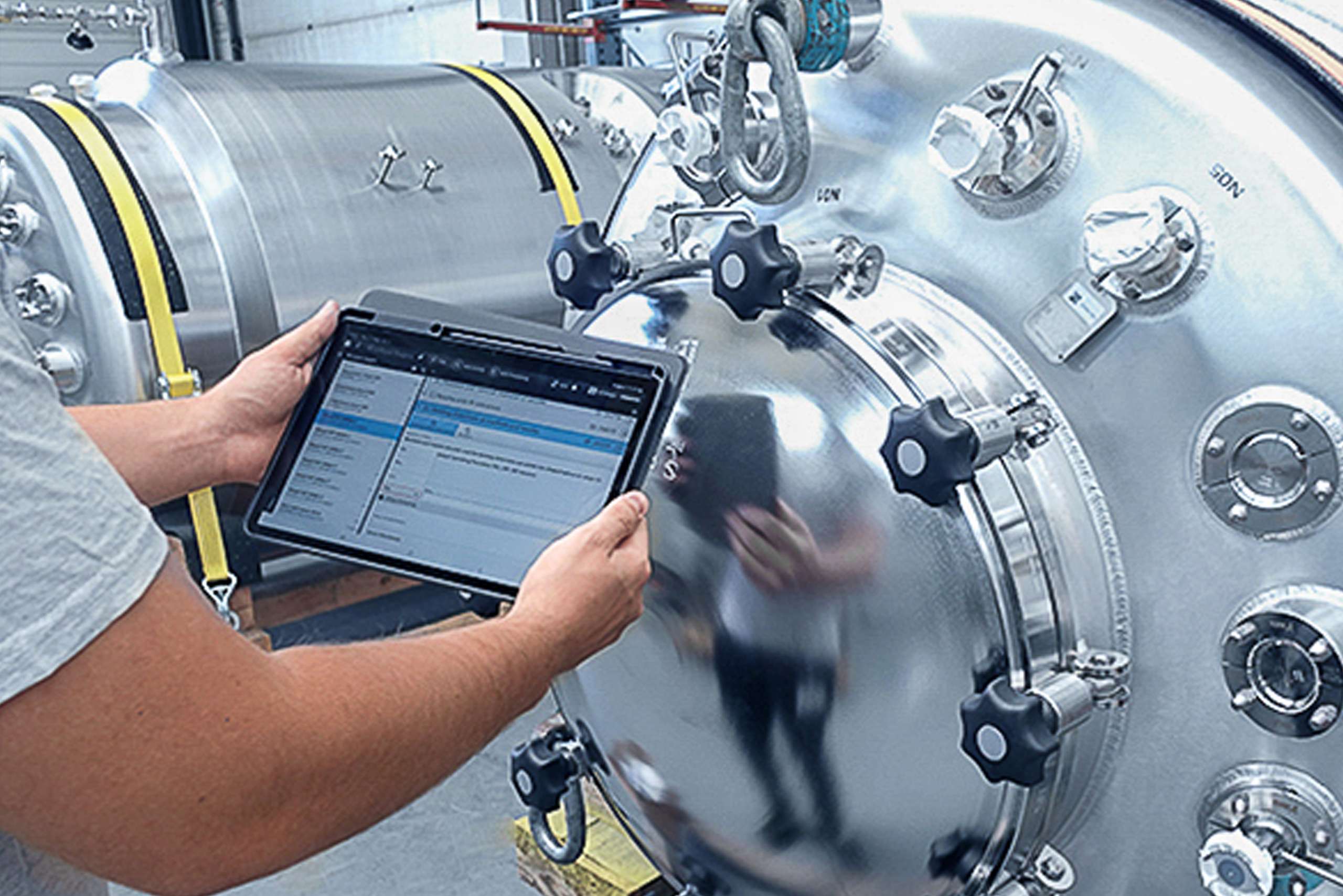
8) CNC Machining, Nozzles, and Dimensional Verification
Many vessels require machining for sealing faces, nozzle interfaces, and instrument connections. CNC machining is commonly used for repeatable flange faces and bolt patterns.
Dimensional control includes checks for:
- Roundness and straightness of the shell
- Nozzle orientation and projection
- Flatness of mating faces
- Support alignment for installation and lifting
This step reduces site rework and helps the vessel integrate cleanly into process systems such as heat exchangers, storage vessels, and skid piping.
9) Pressure Test: Hydrostatic Testing (or Pneumatic, Where Justified)
Before release, the vessel is pressure tested to prove leak‑tightness and structural integrity. Hydrostatic testing is most common because water stores less energy than compressed gas.
Test pressure is defined by the applicable code and conditions. Under ASME Section VIII, hydrotest pressure (at the top of the vessel) is typically at least 1.3 × MAWP multiplied by the ratio of allowable stresses at test vs design temperature (and then corrected for static head where applicable), so it is not a single fixed number for all vessels.
Where water is unacceptable (for example, contamination or drying constraints), pneumatic testing may be used, but it requires strict safety controls due to stored energy.
10) Surface Preparation and Coating: Sandblast, Primer, and Paint
For carbon steel vessels, surface treatment often includes sandblast (or equivalent abrasive blast) to the specified cleanliness grade, followed by a coating system. A typical route includes primer and paint matched to operating conditions, environment, and client specifications.
For stainless steel, finishing may include pickling and passivation (service‑dependent). Linings or cladding may be specified for corrosive substances or where long service life is required.
11) Certification Package and Handover
The final deliverable is not only the steel — it is the vessel plus its proof pack. A typical handover dossier includes:
- Design calculations, drawings, and nameplate details
- Material certificates and traceability maps
- Welding documentation (WPS/PQR and qualifications)
- NDT/NDE reports and repair records
- Heat‑treatment charts (if applicable)
- Hydrotest certificate and final inspection release
In many cases, third‑party inspection is required to support compliance and safety‑critical certification.
Advantages for Customers
- Predictable compliance: code‑aligned steps reduce approval risk and late rework.
- Traceable quality: documentation ties materials, welding, and inspection results to the final asset.
- Reliable performance: controlled forming, welding, and testing support long service life.
- Smoother installation: dimensional control and machining reduce site modifications.
- Lower lifecycle risk: proof‑led inspection gates reduce in‑service failures.
Common Pitfalls (and How to Avoid Them)
- Unclear design basis: lock design requirements early to prevent redesign.
- Under‑specified corrosion strategy: confirm material choice, corrosion allowance, and coating/lining needs.
- Weak traceability: insist on heat number control from raw material to final assembly.
- Late nozzle/internals changes: finalise the nozzle schedule early to reduce rework.
- Treating inspection as an afterthought: integrate testing and inspection into the fabrication process from day one.
Conclusion
The pressure vessel manufacturing process is a controlled route from vessel design through fabrication, inspection, and certified handover. By combining traceable materials used, qualified welding, code‑aligned non‑destructive testing, and a properly defined pressure test, manufacturers reduce risk and protect long‑term integrity. The most dependable outcomes come from clear technical specifications, disciplined quality gates, and manufacturing that is built around real operating conditions. When those pieces are in place, every pressure vessel arrives ready for installation — and ready for safe service.